It is one type of electromagnetic relay so faraday's law of electromagnetic induction is used for relaying action. Induction disc type of relay has further classified into two type based on it's construction. But here only one type is discussed.
Shaded Pole Structure
Design:- You can always have WHY factor when you are analyze it's design. That't the most important part of it's design.
There is 3 Main torque for the operation of the relay as below.
1. Operating torque
2. Restraining torque
3. Damping torque
 |
| Fig-1, Induction disc type relay |
You can see induction disc type relay it has many part in it. Let's Analyze one by one by dismental it.
1. Current Coil
This relay is current operated so CT Connection is directly connected to current coil. You can also see C Shape, One leg of C shaped piece wound by coil. It provide Operating torque to alluminium disc. Design of coil is based upon your CT Secondary current rating(1A or 5A).
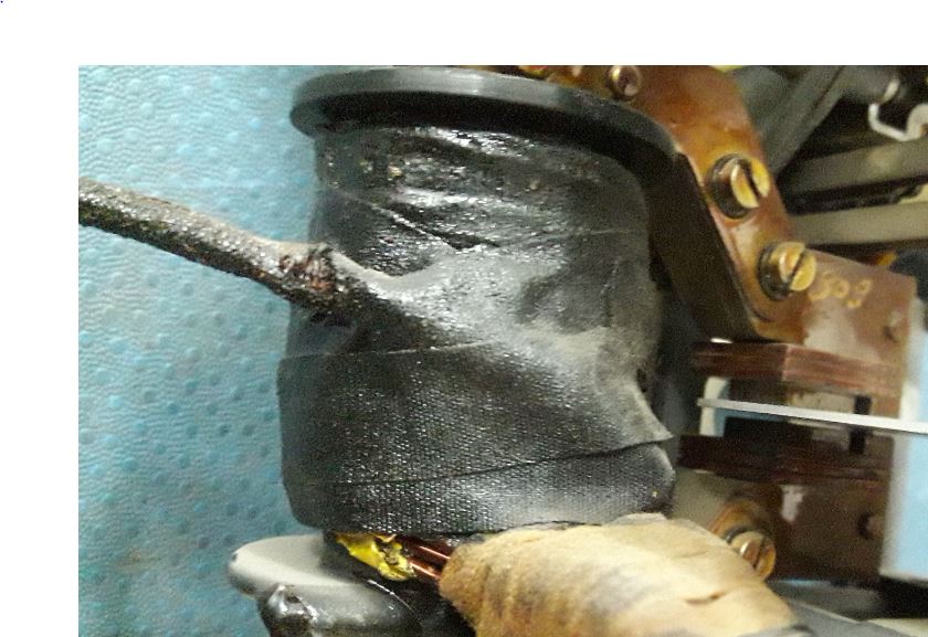 |
| Fig-2, Current coil |
2. Alluminium Disc
This part is heart of relay. Relaying action done by it's rotation. So purpose is to rotate alluminium disc. It's shape is spiral because to compensate against varying restraining torque of the control springs which winds up as disc rotate to close its contact. You can see one alluminium rod it is used to close the NO Contact.
 |
| Fig-3, Alluminium disc |
3. Shaded Pole
Two different flux is needed to generate torque in disc so shaded pole is used to create phase difference between two flux. Shaded portion flux always lag to unshaded portion flux.
 |
| Fig-4, Shaded Pole |
4. Control Spring
It provide restraining torque to alluminium disc. When no current flows through current coil control spring keep alluminium disc at it's reset position.
 |
| Fig-5, Control Spring |
5. Permanent Magnet
It is used to provide damping torque to alluminium disc, for simple language it control speed of disc.
6. Auxiliary attracted armature type unit
Nowadays induction disc type relay is came with this unit already mount on it. It has coil and NO. NC Contact which is going to operate your master trip relay.
These parts is must to successfully rotation and controlling of relay.
Working:-
When current flow in current coil flux induce in that C shape iron. As you see it is not plane C some part is shaded through shaded ring to create two flux.
 |
| Fig-6, Diagram of two fluxes |
As you can see,from normal part(phi)u flux create and from shaded pole(phi)s flux create. Both flux has phase difference.torque in disc is directly proportional to that phase difference HOW?
 |
| Fig-7, Phasor diagram |
As seen from above equation torque is direct proportional to both fluxes and angle between those flux to increase torque either you need to increase flux or increase angle between them. But once shaded pole fix,angle between both fluxes become constant so you need to increase flux if you want to operate your relay fast.
Some term regarding induction disc type relay:-
1. Starting current:- Minimum Current required to start the rotation of alluminium disc.
2. Closing current:- At starting current contact of that disc not closed,to close that contact more current required than starting current so Minimum current required to close the contact of alluminium disc is called closing current.
When no current flowing in current coil, Alluminium disc back to it's original position by restraining spring force.
Problem came in this type of relays:-
This type of relays are tested once in a year because you can see that there is various moving part if one of the part not working properly then your machine is in danger. I have listed some problem as per my experience,
1. Current coil damaged.
2. Disc is jammed due to bearing.
3. Disc not rotate at it's rated starting current.
4. Produce humming sound while rotating.
5. Attracted armature type unit coil open.
Where is the bearing in this?
ReplyDeleteIn the middle of TMS dial.
DeleteThanks for reading.
Thanks for reading.
ReplyDeletePost a Comment