Synchronous machine is most cool and complex machine in Electrical Engineering. It is doubly excited machine which make it complex. Synchronous machine has 3 phase AC Distributed winding on Stator and DC Concentrated winding on rotor. It has two type cylindrical machine and salient pole machine.
I know you already know this facts.So In this post i will discuss about working principle of synchronous machine which is most important in Electrical Engineering. I believe, if someone ask this in your "sleep inertia" at that moment you should be able to speak it flawlessly. And if you can't then you should become "insomniac".
So let's take one 4 pole salient pole synchronous machine and rotate it in clockwise direction by prime mover. Magnetic field of rotor originate form North pole and enter in south pole. It completes its path through low reluctance Stator core.
Motionally induced emf principle says that, When any conductor cut magnetic field then an emf induced in it and polarity of induced emf is given by Right hand palm rule for Generator and Left hand palm rule for Motor.
Take top most conductor, Put your right hand palm perpendicular to magnetic field (Front facing north pole) then adjust your thumb in the direction of motion of conductor(but wait, here conductor are steady so we will assume that rotor is steady and stator rotates in reverse direction i.e.anticlockwise). So thumb will be directing anticlockwise (in tangential direction) in this condition our finger will point out the direction of induced EMF (i.e. from positive to negative potential). By this we can find the polarity of EMF and the current flowing through (same as EMF) each conductor.
Magnetic field of current carrying conductor is founded by right hand rule (Rule of screw). Put your thumb in current direction and curl your finger will show the direction of magnetic field around the conductor. vice versa is also true, you can find current from magnetic field in loop..
By right hand rule we can draw the magnetic field formed by each conductor as shown in the below figure, We can see that between two conductors (in the core of stator) poles are formed. As magnetic field from two consecutive conductors adds up in that region. Polarity of pole is decided by observing the direction of field lines. Magnetic field lines coming out from the stator and entering the rotor can be compared with a magnetic north pole so that will be North pole and for field lines entering into stator can be said as South pole.
Stator pole should be equal to Rotor pole; this is a necessary condition for the induction of EMF and rotation of machine.
Now if we see the poles are arrange in a manner such that they will apply some force on each other. N-N & S-S will repel while N-S will attract each other. As a consequence it will tend to rotor to rotate anticlockwise - this is known as Electromagnetic torque. However rotor is rotated in clockwise direction by prime mover so this electromagnetic torque will oppose the rotor and we have to do "Work" to keep rotor in rotating condition this will require mechanical energy (i.e. provided by steam through turbine) and by as the rotor rotates it generate voltage that creates current and we get electrical energy at output.
Dynamic equation of generator:-
Where, J = moment of inertia.
dw/dt = angular acceleration.
Tpm = Prime mover torque.
Tem = Electromagnetic torque.
This is the balanced condition of synchronous generator in which rotor rotates at constant speed (this condition is necessary to keep the frequency constant, which is the most critical parameter of power system or more specifically for grid, If it varies then it can cause severe damage or a "Black-out" condition). This is consequence of constant input and constant output (i.e. Electric current/load). However at each second the electric load keep changing so it will change the output of the machine and from the above discussion we can say that to keep the machine in steady state we will have to change the input according to output.
The above equation shows the relation between electromagnetic torque and mechanical/prime mover torque with respect to its inertia and angular acceleration. As the balance between the two torque become unbalance, the rotor starts accelerating or decelerating.
If load reduces then steam input also be reduced and vice-versa. In a practical generator electric load always keep varying due to unpredictable nature of load. So according to that change input has to be changed. This change in output is sensed and this feedback is given to the input steam control valve, this mechanism is known as governor.
This brief discussion on stability is not even "A B C D..." of stability. Synchronous generator stability is responsible for the whole grid's stability. This study is known as Power system dynamic and control, And it's a currently the most entertained and researched topic in electric world.
Some important angles in Synchronous machine:-
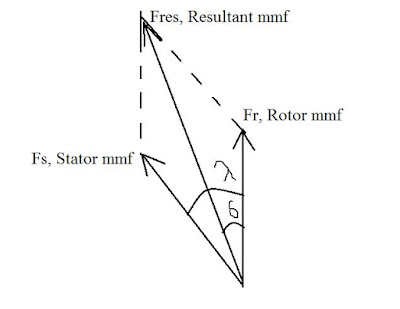
If we draw phasor of stator mmf and rotor mmf than it will become as below.
 |
| Fig -3 Phasor diagram of mmf |
Where, λ = Torque angle
δ = load angle, power angle
This principle applies in motor too. In motor prime mover is replaced by some mechanical load which we want to drive Hence In motor Electromagnetic torque which is produce by motor and rotation is in same direction and load torque oppose it.


Post a Comment